Restoring ATmega128 Bootloader
There are lot of weird things about ATmega128, that I will be covering in this tutorial. The end goal is to set it up properly so that it will be useful and save you some time eventually.
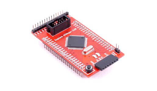
If you have Explore Atmega128 breakout board you need not do any of this!
SPI programming pins
If you're using a board that comes with a 5x2 FRC header, you will not have to worry about this one because the manufactures would have already taken care of this issue. However if you're trying to design a board with atmega128 inside it, read this bit carefully. The atmega128 uses RX0 and TX0 pins instead of MOSI and MISO spi pins for programming in SPI mode. Yes, you read that right! If you're wondering, why I am not able to program the chip, this is the reason.
Fuse Bits
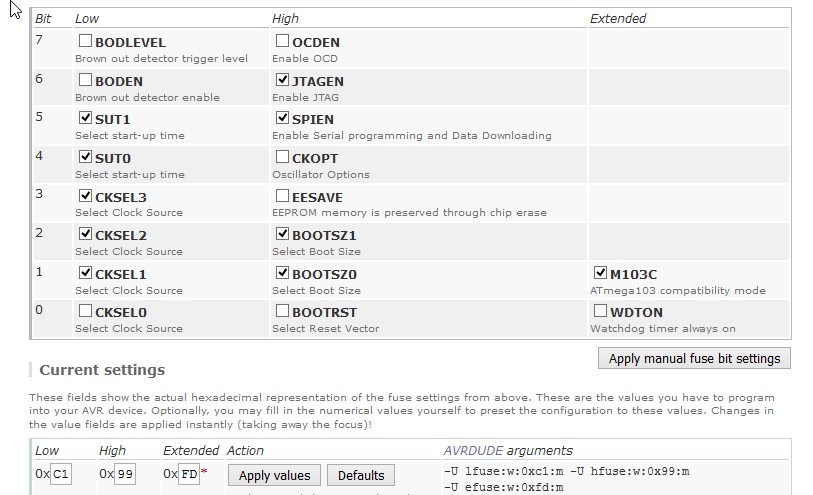
Default Fuse Bits
- By default Atmega128 ships with Atmega103 compatible mode as shown in the image below. Now, with this thing you'll not be able to use the UARTs (serial ports) of Atmega128!
- Oscillator:As with other AVRs by default the MCU runs on 1MHz internal oscillator.
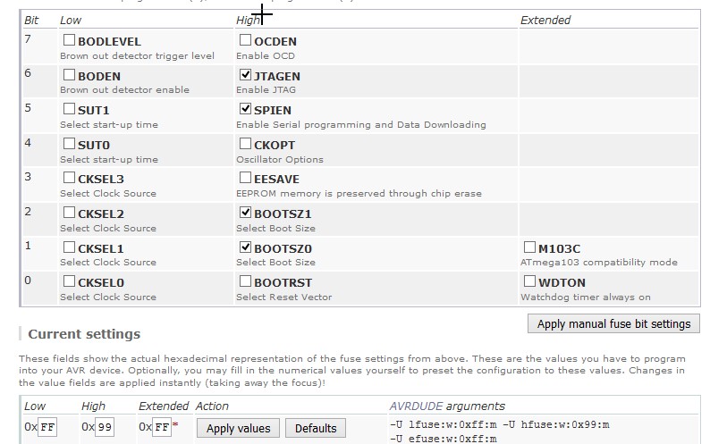
Correct Fuse Bits.
We correct the above two points and ship the MCU with the following fuse bits.
Comment below if you've any other questions!


