Setting up ATmega128 Breakout
In this tutorial we will look at the basic setup required to get started with Atmega128 Breakout. After completion of this basic setup we can interface peripherals with the breakout board.
Basics
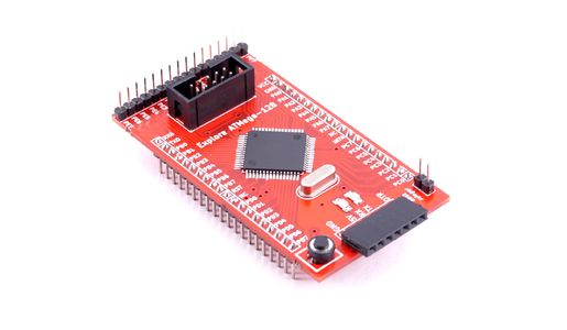
The breakout board has ATmega128 MCU with pre-flashed UART bootloader, so it eliminates the need of external programmer. This breakout board comes with male header soldered so it can be fit easily on breadboard and perf board. Figure below illustrates the various important components on the board.
HookUp
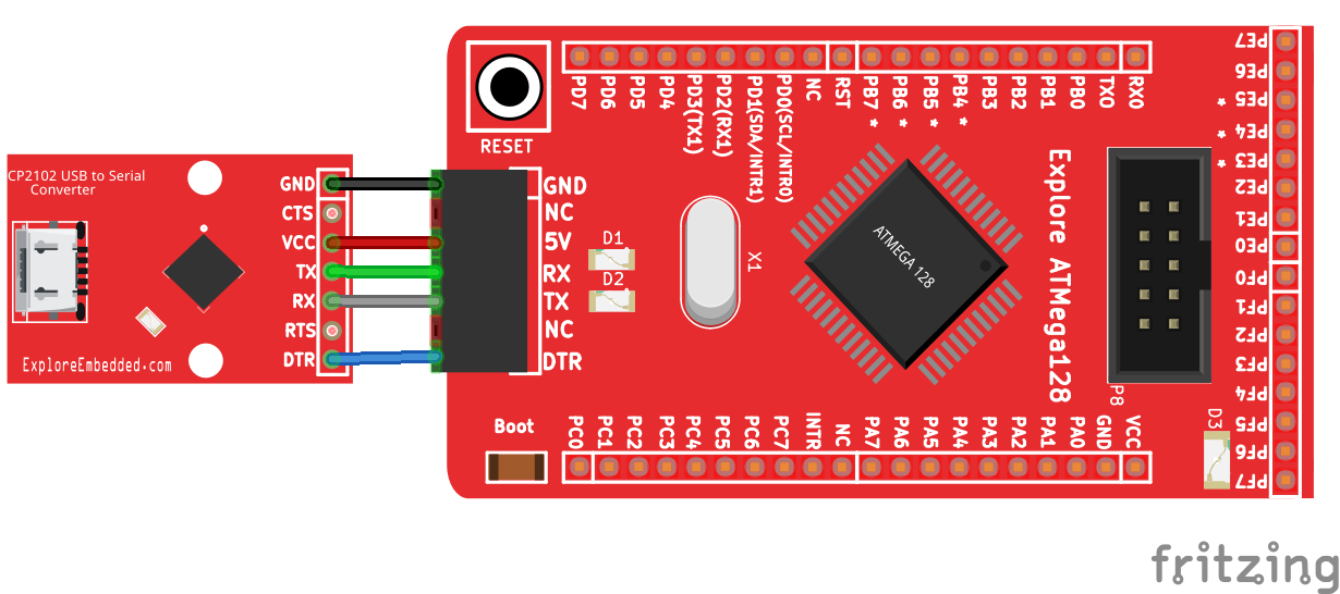
We use the external USB to Serial breakout for flashing the program through serial port. Connect this breakout to USB to serial header of AVR breakout board indicated as '1' in above diagram. The hookup for USB to Serial is shown below:
Software Setup
In this tutorial series we are using Xplore Flash to transfer the hex file to the target MCU. Steps below show how to trasfer the hex file to the MCU using Xplore Flash.
- Open the Xplore Flash and select programmer as Arduino .
- Connect the AVR breakout board to computer through USB to serial breakout so it will detect as a COM port.Select a COM port and set baud rate 19200 .
- Click on "detect" ,it will detect the MCU as ATmega32.
- After detecting the MCU browse the hex file .
- Then just click on Go. it will erases, Flashes and verifies the hex file.
Checkout the Blinky with AVR Breakout tutorial, on how to set up the software, generate a hex file and blink an LED.


