
UART Programming with Atmega128
In this tutorial we are going to learn how to communicate with PC using UART protocol. Atmega128 has two USART, USART0 and USART1. For more information about basics of UART refer AVR tutorial. We will discuss in this tutorial about USART0 thoroughly.
Contents
UART Module
Atmega128 has two UART are named USART0 and USART1. Each UART has Receiver and Transmitter pins which are name as RXD0 and TXD0 for USART0 and similarly RXD1 and TXD1 for USART1. Atmega128 has multiplexed pins so we configure these if we want to use UART's. Below table shows the multiplexed pins related to UART.
| Port Pin | Pin no. | Port Function | Port Function |
|---|---|---|---|
| PE0 | 2 | PDI | RXD0 |
| PE1 | 3 | PDO | TXD0 |
| PD2 | 27 | INT2 | RXD1 |
| PD3 | 28 | INT3 | TXD1 |
UART Register
The below table shown registers are associated with Atmega128 UART.
| Register | Description |
|---|---|
| UDR | USART Data Register |
| UCSR0A | USART0 Control and Status Register A |
| UCSR0B | USART0 Control and Status Register B |
| UCSR0C | USART0 Control and Status Register C |
| UBRR0L | USART0 Baud Rate Register L |
| UBRR0H | USART0 Baud Rate Register H |
UART Register Configuration
We will see now how to configure the UART registers.
| UCSR0A | D7 | D6 | D5 | D4 | D3 | D2 | D1 | D0 | |||||||
|---|---|---|---|---|---|---|---|---|---|---|---|---|---|---|---|
| RXC0 | TXC0 | UDRE0 | FE0 | DOR0 | UPE0 | U2X0 | MPCM0 | ||||||||
This bit is used to show the status of the received buffer.
Bit 7 - RXC0 : USART Receive complete
1 : Unread data in the Receiver buffer
0 : Receive buffer is empty.
This bit us used to show the status of the transmitted buffer.
Bit 6 - TXC0 : USART transmit complete
1 : No data present in the buffer register to transmit
0 : Transmit complete interrupt is executed.
This bit indicates whether Transmit data buffer ready to receive new data.
Bit 5 - UDRE0 : USART Data Register empty
1 : Transmitter buffer is empty
0 : Transmitter is ready.
This bit us used to show the Frame error.
Bit 4 - FE0 : Frame error
1 : Next character in the receiver buffer had error
0 : Writing to UCSR0A.
This bit us used to show the Receiver data over run occure.
Bit 3 - DOR0 : Data over run
1 : Receiver buffer is full (Receiver data over run occure)
0 : Writing to UCSR0A.
This bit us used to show the parity error.
Bit 2 - UPE0 : Parity Error
1 : Next character in the receiver buffer had a parity error
0 : Writing to UCSR0A.
This bit has effect for the Asynchronous operation. For Synchronous operation write this bit to 0.
Bit 1 - U2X0: Double the USART transmission speed
1 :Reduces the divisor of the baud rate divider from 16 to 8 effectively doubling the transfer rate of Asynchronous communication
0 : Synchronous operation.
This bit enables the multiprocessor communication.
Bit 0 - MPCM0: Multiprocessor communication mode
1 :All the incoming frames received by the USART Receiver that do not contain address information will be ignored.
0 : Writing to UCSR0A.
| UCSR0B | D7 | D6 | D5 | D4 | D3 | D2 | D1 | D0 | |||||||
|---|---|---|---|---|---|---|---|---|---|---|---|---|---|---|---|
| RXCIE0 | TXCIE0 | UDREIE0 | RXEN0 | TXEN0 | UCSZ20 | RXB80 | TXB80 | ||||||||
This bit is used to show the status of the received interrupt.
Bit 7 - RXCIE0: RX Complete Interrupt Enable
1 : A USART0 Receive Complete interrupt will be generated
0 : no interrupt.
This bit us used to show the status of the transmitted interrupt .
Bit 6 - TXC0 : USART transmit complete
1 : A USART0 Transmit Complete interrupt will be generated
0 : no interrupt.
Bit 5 - UDRIE0: USART Data Register Empty Interrupt Enable
1 : enables interrupt on the UDRE0 flag
0 : no interrupt.
Bit 4 - RXEN0: Receiver Enable
1 : The Receiver will override normal port operation for the RxDn pin
0 : Receiver will flush the receive buffer invalidating the FEn, DORn and UPEn flags.
Bit 3 - TXEN0: Transmitter Enable
1 : The Transmitter will override normal port operation for the TxDn pin
0 : the Transmitter will not become effective until ongoing and pending transmissions are completed
Bit 2 - UCSZ02: Character Size
1 : number of data bits (character size) in a frame the Receiver and Transmitter use
0 :nil
Bit 1 - RXB8n: Receive Data Bit 8
RXB8n is the ninth data bit of the received character when operating with serial frames with 9-data bits. Must be read before reading the low bits from UDR0.
Bit 0 - TXB8n: Transmit Data Bit 8
TXB8n is the 9th data bit in the character to be transmitted when operating with serial frames with 9 data bits. Must be written before writing the low bits to UDR0.
| UCSR0C | D7 | D6 | D5 | D4 | D3 | D2 | D1 | D0 | |||||||
|---|---|---|---|---|---|---|---|---|---|---|---|---|---|---|---|
| URSEL0 | UMSEL0 | UPM10 | UPM00 | USBS0 | UCSZ10 | UCSZ00 | UCPOL0 | ||||||||
This bit is used to show the status of the received interrupt.
Bit 7 - Reserved Bit
This bit selects between Asynchronous and Synchronous mode of operation.
Bit 6 - UMSEL0: USART Mode Select
1 : Synchronous Operation
0 : Asynchronous Operation.
These bits enable and set type of parity generation and check
Bit 5:4 – UPM01:0: Parity Mode
| UPM01 | UPM00 | Parity Mode |
|---|---|---|
| 0 | 0 | Disabled |
| 0 | 1 | (Reserved) |
| 1 | 0 | Enabled,Even parity |
| 1 | 1 | Enabled,odd parity |
This bit selects the number of stop bits to be inserted by the Transmitter. The Receiver ignores this setting.
Bit 3 - USBS0: Stop Bit Select
1 : 2-bits
0 : 1-bit
The UCSZ01:0 bits combined with the UCSZ02 bit in UCSR0B sets the number of data bits (character size) in a frame the Receiver and Transmitter use.
Bit 2:1 - UCSZ01:0: Character Size
| UCSZ02 | UCSZ01 | UCSZ00 | Character Size |
|---|---|---|---|
| 0 | 0 | 0 | 5-bit |
| 0 | 0 | 1 | 6-bit |
| 0 | 1 | 0 | 7-bit |
| 0 | 1 | 1 | 8-bit |
| 1 | 0 | 0 | Reserved |
| 1 | 0 | 1 | Reserved |
| 1 | 1 | 0 | Reserved |
| 1 | 1 | 1 | 9-bit |
This bit is used for synchronous mode only.
Bit 0 - UCPOL0: Clock Polarity
1 : Synchronous
0 :Asynchronous
| UBRRH | UBRRL | ||||
|---|---|---|---|---|---|
| D15 | D14 | D13 | D12 | D11:D8 | D7:D0 |
| URSEL | - | - | - | UBRR[11:8] | UBRR[7:0] |
♦ Bit 11:0 - UBRR11:0: USART Baud Rate Register
This is a 12 bit register which contains the USART baud rate. The UBRRH contains the four most significant bits, and UBRRL contains the 8 least significant bits of the USART baud rate.
Baud Rate Calculation
Baud rates for asynchronous operation can be generated by using the UBRR settings. Oscillator frequency(fosc) and baud rate needs to put in below formula for UBRR value generation.
$$UBRR = fosc - (Baudrate * 8)/Baudrate * 16 $$
Let us calculate UBRR value,
Given oscillator frequency is 16MHz and required baud rate is 9600.
$$UBRR = 16M - (9600 * 8)/9600 * 16 $$
$$UBRR = 103$$
Steps for Configuring UART0
Below are the steps for configuring the UART0.
- Step1: The USART has to be initialized before any communication can take place. Enable Receiver and Transmitter by configuring UCSR0B register.
- Step2: Select the Asynchronous mode by configuring UCSR0C register.
- Step3: Clear the USART status register by configuring UCSR0A register.
- Step4: Set the baud rate by configuring UBRR register.
After this the UART will be ready to Transmit/Receive Data at the specified baudrate.
Code for Transmitting Char
Code for Receiving Char
Code
Below is the code for transmitting and receiving chars at 9600 baud
Using Explore Embedded Libraries
We have shown above how to configure the UART0 and written small code for transmitting string to pc. Now we will see how to print the string on hyper terminal using Explore Embedded libraries. Our below code covered both the channels (UART0 and UART1).
Testing
Make the connections as per below image. We have shown below only for UART0 connections. For UART1 you need to connect the PD2 ( RXD1) to USB to Serial Converter TXD and PD3 (TXD1) to Serial Converter RXD.

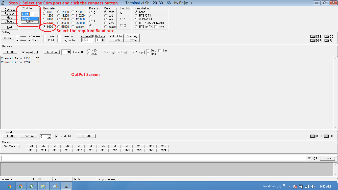
Open the terminal software , select the COM port, set baud rate and hit the connect button.
Video Tutorial
For those of you, who would like to watch instead of read we have made a video with all the gyan.
Downloads
Download the complete project folder from the below link:
https://github.com/ExploreEmbedded/ATmega32_ExploreUltraAvrDevKit/archive/master.zip
Have a opinion, suggestion , question or feedback about the article let it out here!