Difference between revisions of "PIR motion Sensor interface with Atmega128"
Raghavendra (Talk | contribs) |
|||
| Line 48: | Line 48: | ||
[[File:0PIR sensor.jpg|none]] | [[File:0PIR sensor.jpg|none]] | ||
| − | { | + | =Video Tutorial= |
| + | For those of you, who would like to watch instead of read we have made a video with all the gyan. | ||
| + | <br> | ||
| + | {{#ev:youtubehd|-lNAmSNV2-Q|640}} | ||
| + | |||
| + | |||
| + | = Downloads= | ||
| + | Download the complete project folder from the below link: | ||
| + | https://github.com/ExploreEmbedded/ATMega-128-Break-Out-BoardDVB-12007/archive/master.zip<br> | ||
| + | |||
| + | |||
| + | |||
| + | Have a opinion, suggestion , question or feedback about the article let it out here! | ||
| + | {{DISQUS}} | ||
Revision as of 12:53, 19 April 2016
In this tutorial we will see something interesting sensor which tells your presence Let's see in this tutorial how this sensor basically works?
We will look at a interesting sensor in this tutorial. This sensor will detect motion in the room, automatic door in elevator, automatic lighting system, and washroom amenities.
Contents
Basics
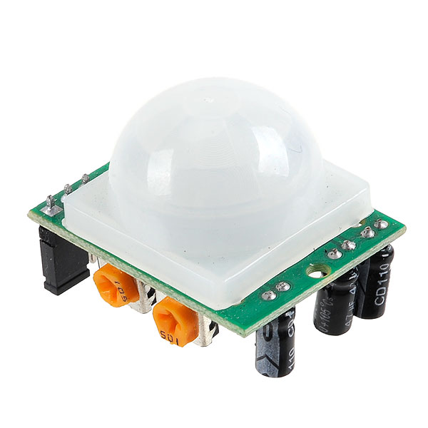
This in expensive sensor allow you to sense the motion and it detects the presence of human being or heat emitting body in its proximity. These are named as Pyroelectric sensor or Passive Infrared (PIR) sensor. Pyroelectricity means heat which generates the electricity. PIR sensors are passive sensor, which means they are not generates infrared energy but they detect the heat energy which is given by other heat emitted body in the form of radiation. The sensor is split into two halves, one detects more or less infrared and turned out into high or low signal. Along with Infrared sensor it consist bunch of other circuit. See below images for reference.
The plastic window is covered on infrared sensor have multiple facets molded into it to focus the infrared energy onto the sensor. Each of these individual facets are called Fresnel lens.
Let us discuss about 3 important settings of PIR sensors in detail.
- Re-triggering setting
- Sensitivity adjustment
- Delay time adjust
Re-triggering setting
As you can, see the Re-triggering section has three SMD pads. . Few PIR sensor modules comes with through hole male pin headers and it is shorted with one of the states either it is in non re-triggering mode or re-triggering mode. We could see the two status High(H) and Low(L) on board. In our case it is default connected to H. The 'L' mode setting behaves erratic, when we move in front of sensor output pin goes high and low again. This is called 'non re-triggering mode'. In 'H' mode setting when we move in infrared proximity the output pin of the sensor will go high. This is called 'Non re-triggering mode' In 'H' mode setting when we move in infrared proximity the output pin of the sensor will go high. This is called 'Re-triggering mode'. This mode of setting is widely used setting.
Sensitivity adjustment
The potentiometer shown in the image above is provided for sensitivity adjustment. If pot is turned clockwise the sensitivity increases, and decreases the other way around.
Delay time adjust
The 'delay time' determines the how much time the output pin of the sensor will keep it high when motion has been detect. The range od the delay time of the sensor become few seconds to few minutes. In our case it become 2 seconds to 200 seconds. Note : For first time of testing the PIR sensor keep delay time less .
PIR Testing
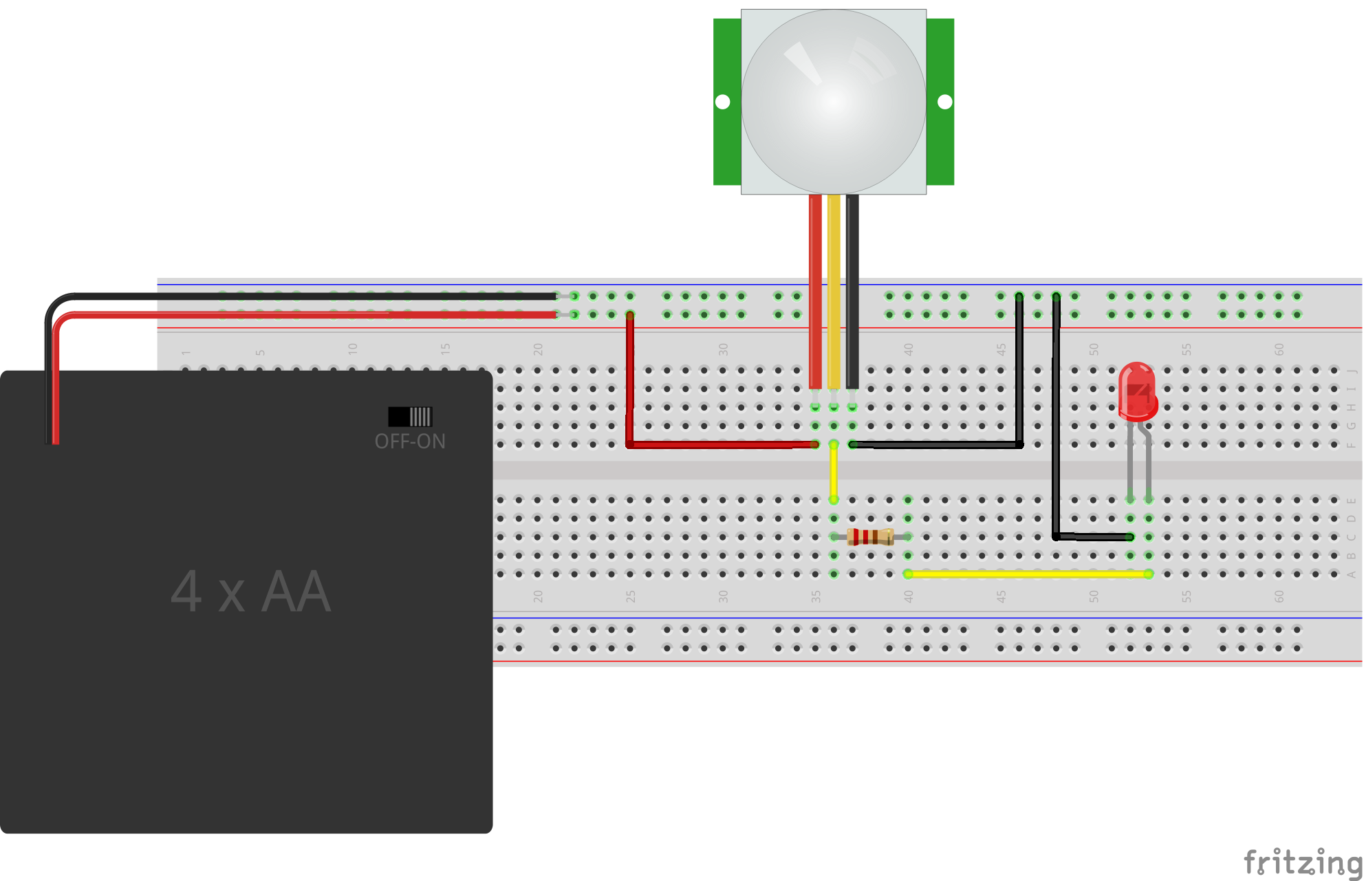
We can test the PIR without interfacing with Atmega128. For this we require a set of batteries,LED,470E resistor and a few wires. Image below shows the hookup.
The above LED will glow when motion is detected and it will turn off when there is no motion.
HookUp
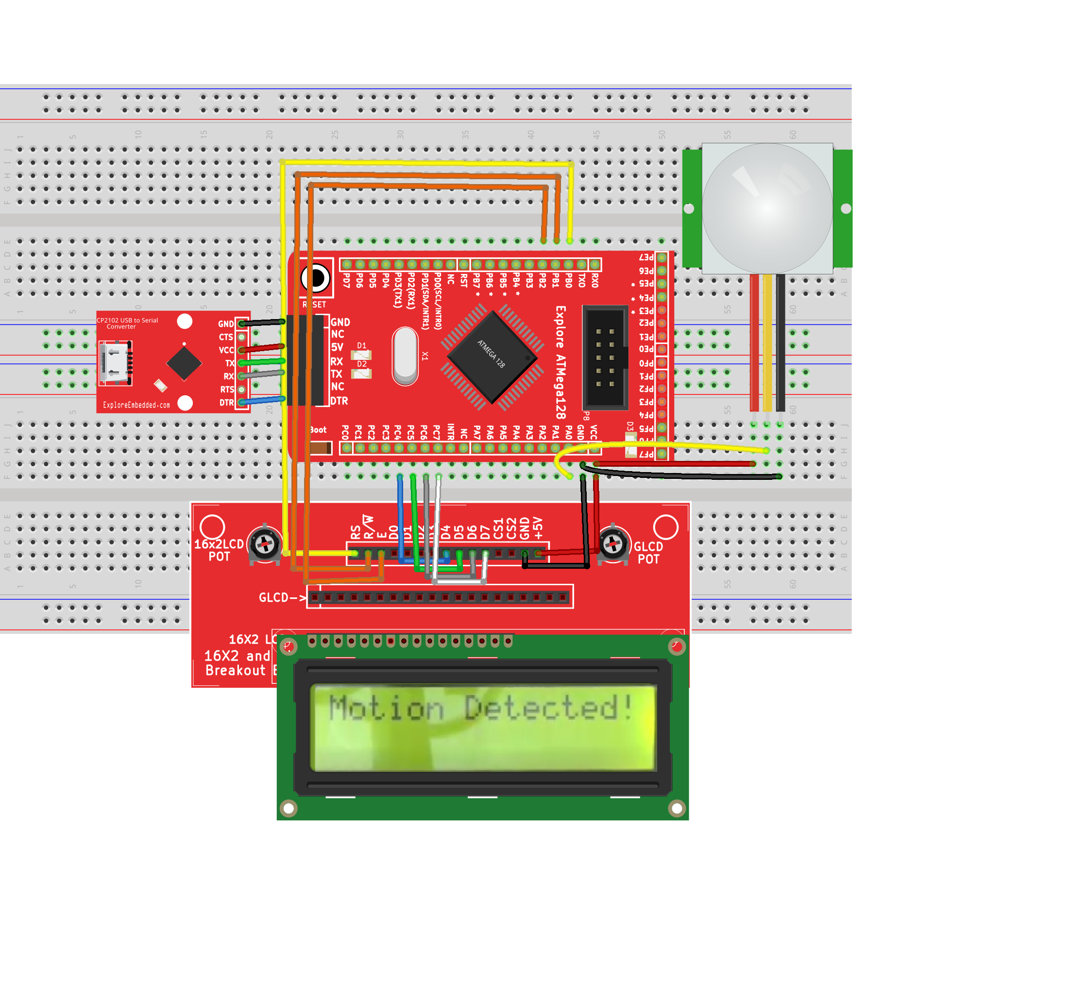
Now let's go ahead and hook up the sensor the Atmega128 board and also use the display to show the motion.
Code
Demo


