Difference between revisions of "Switch and Led with 8051 Starter Board"
Raghavendra (Talk | contribs) |
Raghavendra (Talk | contribs) |
||
| Line 13: | Line 13: | ||
<script src="https://gist.github.com/raghavendrahassy/48af133158f274aee8f20e05a411a329.js"></script> | <script src="https://gist.github.com/raghavendrahassy/48af133158f274aee8f20e05a411a329.js"></script> | ||
</html> | </html> | ||
| + | |||
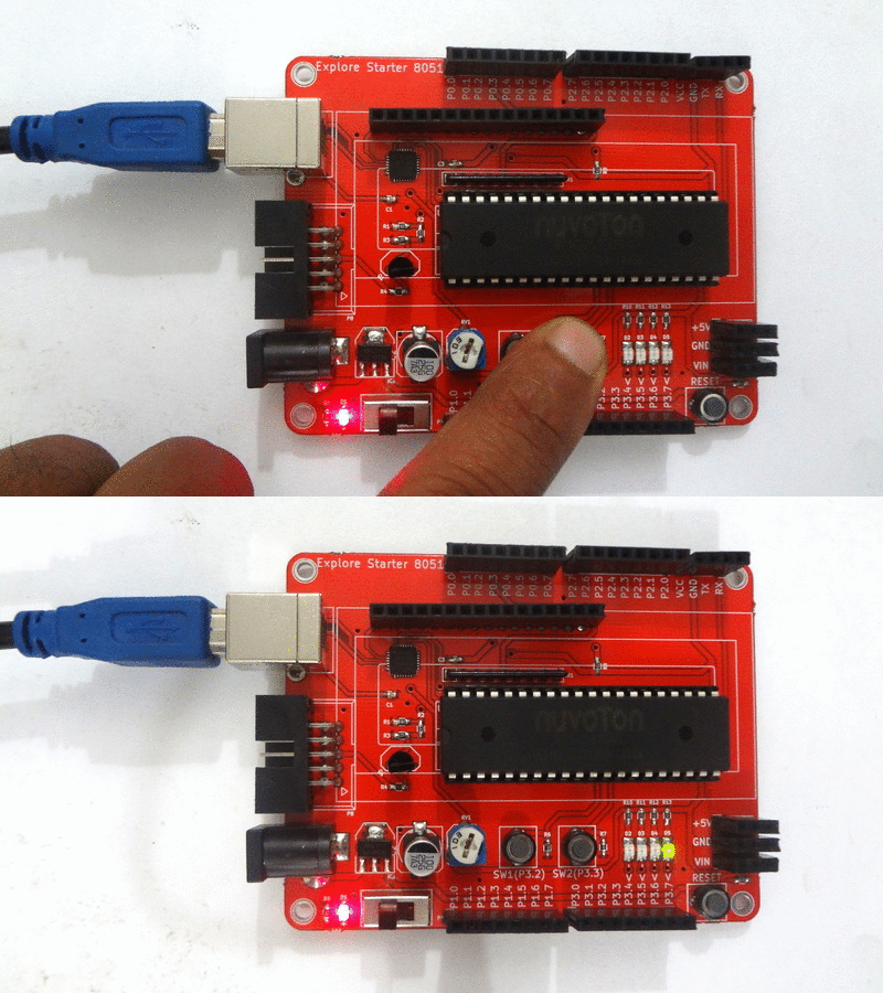
| + | == Demo == | ||
| + | [[File:0LEDSwitch 8051.gif|none]] | ||
Latest revision as of 17:31, 17 June 2016
In this tutorial we will see how to read status of the Switch. Once we read the status of the input will take appropriate action by glowing the on board LED.
Basics
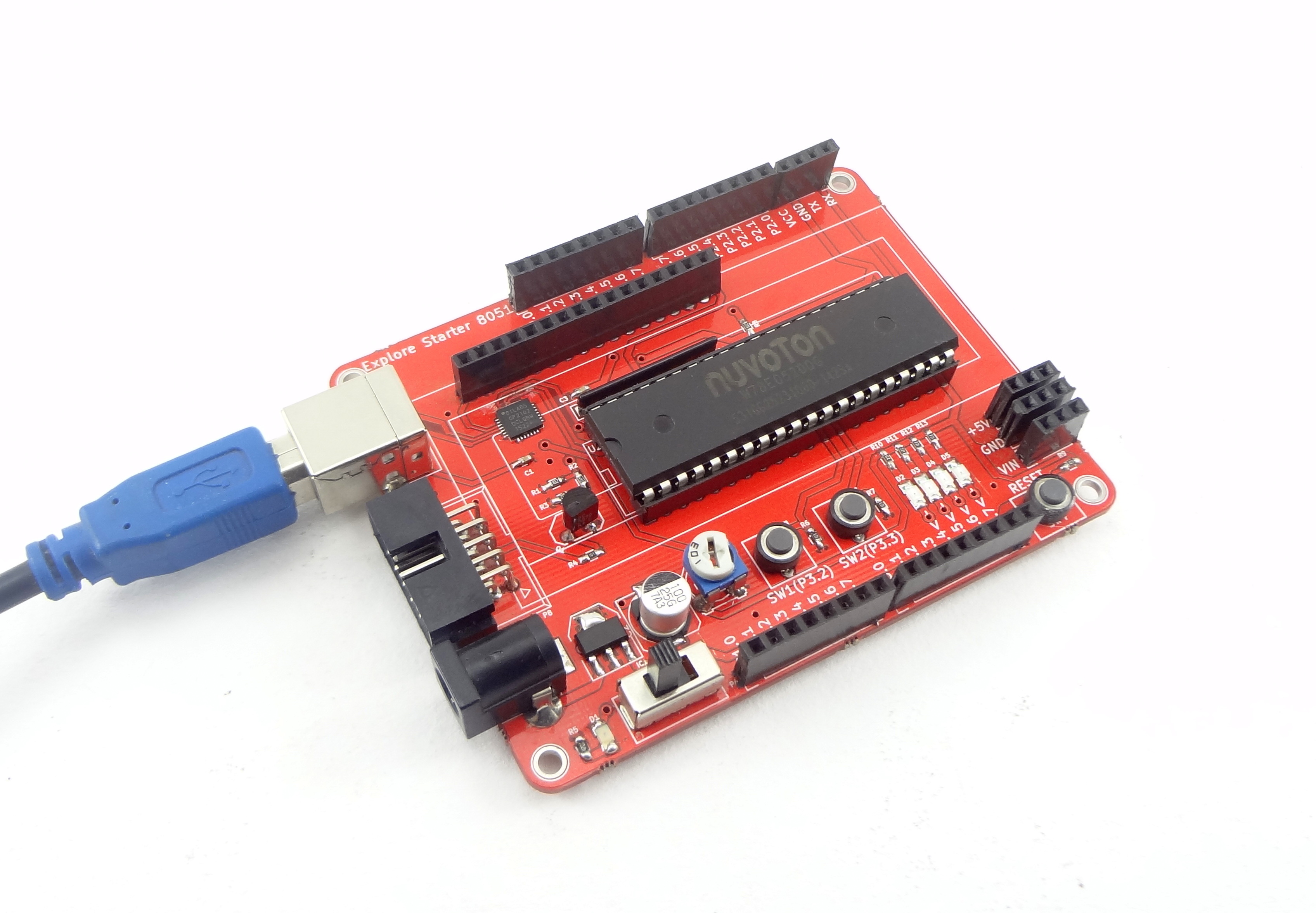
Explore Starter 8051 board has 2 user interface switches on the board which are connected to P3.2 and P3.3 . There are 4 LED's are on board which are also connected to higher four bits of P3. Out of these we will read the status of SW2 ( Connected to P3.3) and will show the status on LED ( Connected to P3.7).
Hookup
Code


