AVR Timer Interrupts Revision as of 11:55, 19 April 2016 by Raghavendra (Talk | contribs)
Contents
Basics
We have covered the basics of AVR timer Programming, during the Timer 1 example we saw that we had to monitor the Flags to check if the Timer has overflown which made the main program dependent on the status of the flags. Timers are independent unit's inside a micro-controller and to make full use of them we will configure and use them with Interrupts. This makes the CPU free from polling the flags and timers can operate on their own. When the timing task is finished, it will interrupt and inform the CPU.
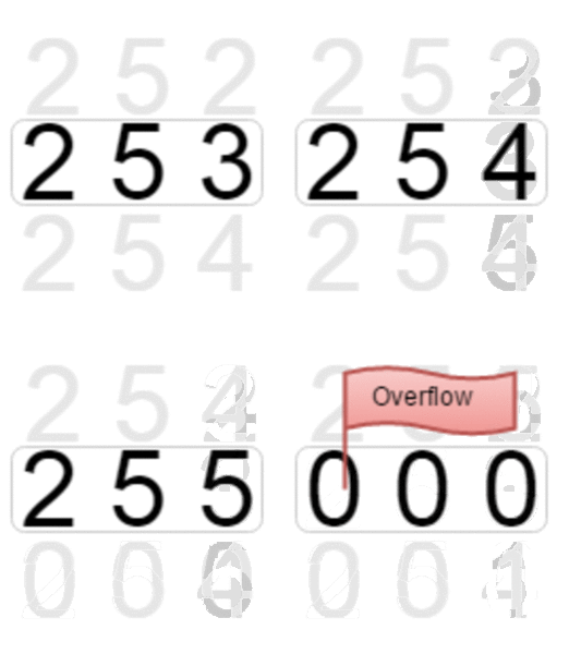
For timer zero, the count goes from 0 to 255 and rolls over. With that the timer over flow flag is set and it can be used to trigger an interrupt.
Let us repeat the same example of blinking a LED connected to PD4 at 100ms delay with Timer 1 but this time using Interrupts. We have covered the Basics of AVR Interrupts, you may wish to go through it first.
All the calculations from the previous tutorial hold good. Except, since we are using the Timer OverFlow flag, the value 65536 - 1562 = 63974 is loaded in TCNT1.
Steps to configure the Timer Interrupt:
- Load the TCNT1 register with the value calculated above.
- Set CS10 and CS12 bits to configure pre-scalar of 1024
- Enable timer1 overflow interrupt(TOIE1), the register is shown below
- Enable global interrupts by setting global interrupt enable bit in SREG
- Toggle the LED in the ISR and reload the TCNT value.
| TIMSK | D7 | D6 | D5 | D4 | D3 | D2 | D1 | D0 | |||||||
|---|---|---|---|---|---|---|---|---|---|---|---|---|---|---|---|
| - | - | TICIE1 | OCIE1A | OCIE1B | TOIE1 | - | - | ||||||||
Code
Look at the while(1) loop, it is happy that there is no code to execute in there ;)
Video Tutorial
For those of you, who would like to watch instead of read we have made a video with all the gyan.
Downloads
Download the complete project folder from the below link:
https://github.com/ExploreEmbedded/ATmega32_ExploreUltraAvrDevKit/archive/master.zip
Have a opinion, suggestion , question or feedback about the article let it out here!

